


Large-Diameter Sewer Pipes: Cracks, Risks, Structural Integrity – What Operators Need to Bear in Mind
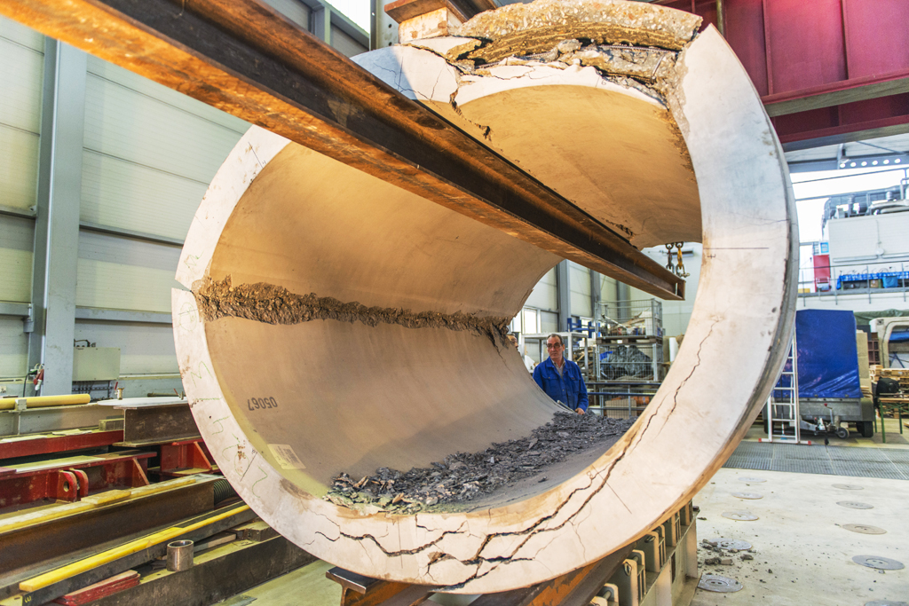
Reinforced concrete pipe after a crown pressure test: crack patterns and load-bearing behaviour are key factors in the assessment and quality assurance of large-diameter pipes.
Large-diameter pipes are high-performance assets – and high-risk ones.
If accessible main collectors fail, there is a risk of backflow, flooding, road collapses and high follow-up costs.
What should network operators look out for in terms of construction quality, inspection, structural integrity and rehabilitation?
And how can they identify weak points in the pipe-soil system?
What network operators can take away from this article
- why large-diameter pipes are particularly high-risk structures in the sewer network,
- which quality requirements are important for new construction and pipe-jacking,
- what matters when inspecting and assessing the condition of large-diameter pipes,
- when special methods such as MAC are appropriate,
- how rehabilitation methods should be selected on a project-by-project basis.

Test setup for crown pressure test: jacking pipe in the IKT test-rig under a large pressure cylinder.
Large-diameter pipes: high performance, high risk
Large-diameter pipes are generally understood to mean walk-in nominal diameters ranging from approximately DN 800 to DN 1000 and larger. They collect and transport large volumes of wastewater and rainwater from entire catchment areas – often beneath major roads, dense urban development or critical infrastructure.
For network operators, three questions are therefore crucial:
- Is the pipeline hydraulically efficient and operationally safe?
- Is the stability of the pipe-soil system guaranteed?
- Is the entire system comprising pipes, joints, connections and bedding permanently watertight?
Large-diameter pipes are not simply standard sewer pipes in a larger size – they present specific risks and require special attention during construction, operation, inspection and rehabilitation.
With accessible main collectors, a great deal is at stake: structural stability, operational safety, consequences at the surface – and the question of whether network operators can identify critical weak points in good time.
IKT test engineer examines crack formation in crown pressure test
Open-cut construction: reinforced concrete, crack formation and minimum reinforcement
For new large-diameter pipes installed in open-cut construction, the focus is primarily on material selection, manufacturing quality and installation conditions. Large-diameter pipes are often constructed as reinforced concrete pipes. Their transport and adequate strength at the time of delivery to the construction site are decisive for subsequent susceptibility to cracking.
Many fine cracks usually indicate a functioning bond and a correctly dimensioned reinforcement design, whilst individual large cracks tend to point to poor pipe quality or substandard manufacturing.

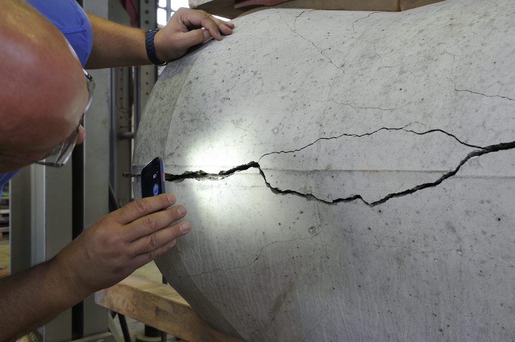
Cracking in reinforced concrete pipe
Operators should therefore explicitly require curing within the formwork (e.g. at least 24 hours) in their tenders to ensure dimensional accuracy and bond quality – this requirement is not yet universally enshrined in standards for standard pipes and remains an additional quality-related requirement on the part of the client.
Similarly, cracks with a width of 0.3 mm should not simply be accepted on site, as this limit value is derived from the crown pressure test and should not be transferred uncritically to embedded pipes, where different stress conditions apply.
Practical point for operators:
Tenders should explicitly require that pipes are allowed to cure sufficiently within the formwork. A curing time of at least 24 hours is recommended. The aim is to achieve better dimensional accuracy and a secure bond between the concrete and the reinforcement.

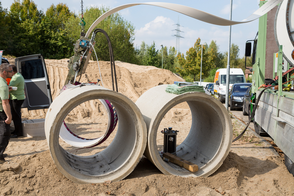
Launch pit for pipe jacking of a main collector
Pipe jacking: pressure transmission elements are safety-critical
In the pipe-jacking method, reinforced concrete jacking pipes are used in particular. They must absorb high compressive forces. In addition to control and ground conditions, the focus here is also on pipe quality, particularly dimensional accuracy (perpendicular end faces, exact dimensions) as a prerequisite for straight, low-stress pipe-jacking operation.
Pressure transmission elements between pipe joints are designed to transmit compressive forces evenly and prevent stress peaks. Earlier solutions using solid timber rings have largely been replaced by OSB boards and other wood-based materials. For tight bends or varying curvatures, more elastic plastics can also be used, sometimes in combination with sheet metal inserts.

Comparison of pressure transmission elements
Large-scale tests conducted by the IKT have shown that the material and thickness of these intermediate layers significantly influence the stress distribution within the pipe string. Cyclic loads during pipe jacking can lead to plastic deformation. These findings have been incorporated into DWA standard A 161, which requires testing of pressure transmission elements.
For network operators, this means:
Pressure transmission elements are safety-critical components. They should be planned, tested, quality-assured and documented – not only once damage has occurred.Damage in the jacking train is often attributable to inadequate pressure transmission components and not primarily to the pipe itself.

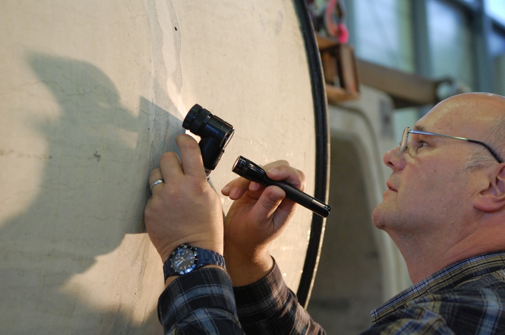
Surveying a masonry sewer
Inspection: Large-diameter pipes require their own concepts
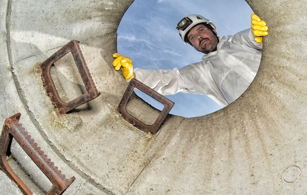
The inspection of large-diameter sewers differs fundamentally from standard CCTV inspection of smaller diameters. Anyone working in large-diameter pipes requires a well-thought-out safety organisation: standby personnel, suitable personal protective equipment, sewer atmosphere monitoring and clearly regulated access conditions.
Technically, it is not just about good images. With large-diameter pipes, additional information is important:
- profile measurement and length recording,
- documentation with photos, video and audio records,
- inspection of joints, masonry and concrete surfaces,
- determination of wall thicknesses and material properties,
- assessment of deformations and bedding effects.
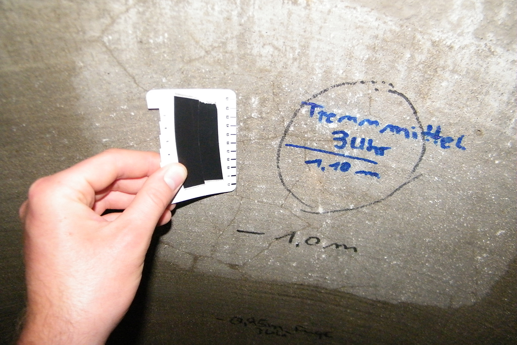
Crack inspection following a crown pressure test at the IKT
In addition to visual assessment, simple but effective tools are recommended:
- Hammer and screwdriver for inspecting joints and masonry (particularly in old masonry sewers)
- Templates for assessing deformations
- Targeted core samples to determine wall thicknesses and material properties
Core samples can provide important information, but are not always feasible without difficulty. In areas with high groundwater levels or in particularly critical locations, adapted drilling strategies and careful sealing of the boreholes are required.
Surface probing is usually difficult due to the density of underground utilities and paved or built-up surfaces, and often provides only limited meaningful information about the immediate pipe environment.
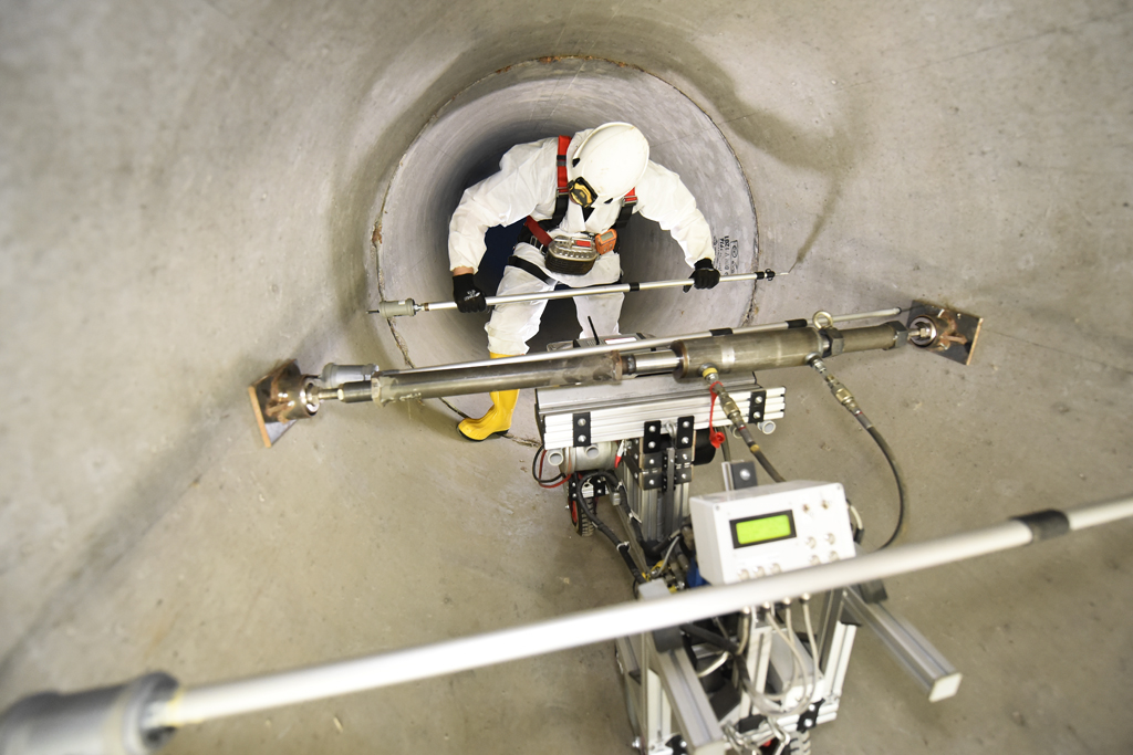
Structural integrity: the MAC method tests the entire pipe-soil system
MAC method: Where is the weak point in the large-diameter pipe?
A key question for operators is: Where is the weak point in the large-diameter pipe?
This is precisely where the IKT’s MAC method comes in. MAC stands for “Mechanical Assessment of Conduits”. The method is used for the non-destructive mechanical assessment of the existing pipe-soil system.
In this process, the pipe is gently pushed apart locally using a hydraulic cylinder and the resulting deformations are recorded at three measurement cross-sections (load point, in front of it, behind it).
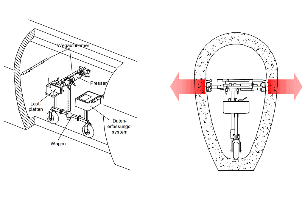
Operating principle of the MAC system
The deformations achieved are within the elastic range (for example, in the tenths of a millimetre range for DN 1500) and do not impair the load-bearing capacity of the pipe. A pipe-soil stiffness can be derived from the force-deformation relationships. This describes not only the condition of the existing pipe, but also the contribution of the bedding.
Measurement intervals of typically 5 metres provide a structured picture along the length of the collectors, showing stiff and less stiff zones, which provides initial indications of potential weak points without the need for extensive calculations.
In a detailed analysis, the influences of the pipe and the ground can be separated and structural verifications carried out – for example, for risk assessment beneath railway lines, high-rise building foundations or at the final collector before the sewage treatment plant.

Results of a MAC test Graphical representation of total stiffness with zoning of a pipe
Due to the effort involved, the method is not intended as a standard inspection, but as a targeted measure for high-risk structures where failure would have particularly serious consequences or where explicit structural verification is required (e.g. by infrastructure operators). More on the IKT’s MAC method
Inspection whilst in operation: when draining is hardly possible
In practice, large collectors cannot always be easily taken out of service or drained. Alternative approaches are required, particularly for collectors that are permanently partially filled.

Inspection drone in a sewer
There are alternative inspection methods for such cases:
- Use of cameras mounted on floating platforms to inspect the gas space, combined with stabilised image guidance.
- Electrical leakage measurement systems (Electroscan) for detecting leaks below the water surface via resistance measurements between the interior and exterior of the pipe.
Such methods do not always provide a complete, standards-compliant condition assessment. However, they can be important components of risk management: identifying critical areas, setting priorities and preparing decisions until a comprehensive inspection is possible.
Given the growing range of drone and floating vehicle systems, the IKT sees this as an important area of innovation for future inspection concepts. See also: IKT International Conference 2026: How AI, Drones, Sensors and Robotics are Transforming Sewer Operations – and What Network Operators Should Prepare For

Infiltration through damaged masonry joints
Rehabilitation: not every method is suitable for every large-diameter pipe
In rehabilitation, a distinction is made between repair, renovation and replacement. For localised damage, open repairs as well as mortar and resin systems are used.
It is not just the “best” material that is crucial. What matters is the combination of suitable material and careful execution.
For masonry sewers, full-surface joint rehabilitation and masonry rehabilitation in particular have become established, as developed and implemented by Düsseldorf City Drainage, amongst others. This involves renewing joints, replacing bricks, grouting cracks and reinforcing the inner shell along its entire length.

MAC in a masonry sewer: preparation for joint rehabilitation
Measurements using the MAC method demonstrated that this ‘Düsseldorf’ structural rehabilitation method can lead to a significant increase in stiffness. This has contributed significantly to its recognition as an investment measure.
Traditional renovation methods include:
- CIPP liners, available according to manufacturers’ specifications in large nominal diameters up to approximately DN 2000
- Short-pipe and single-pipe lining with backfilled annular space
- Segmental and spiral-wound pipe systems
CIPP liners offer the advantage of minimal cross-sectional loss and adapt well to existing cross-sections. Short-pipe and single-pipe lining can be particularly useful where statically effective annular space grouting is required.
Spiral-wound method for sewer pipe rehabilitation
Spiral-wound pipe systems are theoretically considered an interesting option, but have so far been used only rarely in Germany.
Segmented glass linings have had to prove themselves in pilot projects, particularly in terms of the durability and watertightness of the joints, and are viewed critically.
Cracks and corrosion: identify the cause first, then take action
A step-by-step approach is recommended when dealing with cracks in large reinforced concrete pipes. Before any intervention takes place, the cause should always be identified first and the development of the cracks monitored through repeated inspections (e.g. after 3 to 6 years).
Even small cracks must be accurately measured and monitored.
Cracks significantly wider than approximately 0.2 to 0.3 mm require further investigation, particularly if there is water ingress or evidence of reinforcement corrosion.
Minor water ingress in concrete can sometimes seal itself through precipitation. However, this self-healing effect is no substitute for regular inspection. Cracks that are progressing or that keep the reinforcement permanently damp are particularly critical.
Load-bearing capacity problems rarely arise solely due to bending, as circular rings possess large structural reserves. The condition only becomes problematic if the reinforcement fails suddenly as a result of corrosion or if the bedding is significantly weakened.
Accordingly, supplementary investigations of the bedding should be carried out (e.g. dynamic probing) and, where necessary, linings or measures primarily designed to protect the steel should be implemented.
What’s going on in the sewer? Identifying and repairing damage. Take a look inside every now and then!
Conclusion: Large-diameter pipes require active quality control
Large-diameter pipes are among the most critical components of municipal wastewater infrastructure. They must be considered throughout their entire service life – from new construction through operation and inspection to rehabilitation.
For network operators, this means:
- formulate quality requirements for new construction early and clearly,
- consistently test pressure transmission elements and pipe quality,
- plan large-diameter pipe inspections safely and methodically,
- use specialised methods such as MAC in a targeted manner for high-risk assets,
- select rehabilitation methods on a project-by-project basis rather than schematically,
- assess cracks and corrosion in relation to bedding and load-bearing behaviour.
Or, in short: large-diameter pipes do not require a routine approach, but rather attention, specialist knowledge and structured decision-making.
Further reading
Large Diameter Pipes – Repair or Replace? Non-destructive Testing with the MAC System

Dipl.-Ing. Martin Liebscher, Senior Research Fellow IKT
Contact person
Dipl.-Ing. Martin Liebscher
Email: liebscher@ikt.institute
Related Posts
 IKT Comparative Test “Odour filters”
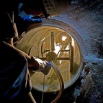 IKT introduces: New Member TOA, Japan
 30 Years of Sewerage Research at IKT – Institute for Underground Infrastructure: What was, what is and what is yet to come
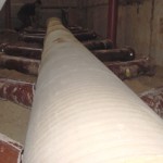 IKT Comparative Test
“Repair methods for sewer lateral connections” Invitation for IKT’s International Friends: Visit us in May!
 IKT research project on optimising sewer cleaning
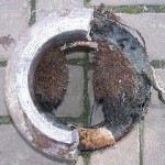 Root intrusion into waste-water sewers – passive preventative measures
Sorry, the comment form is closed at this time.