





Structural Design of CIPP Liners: What Role Does the Host Pipe Really Play?
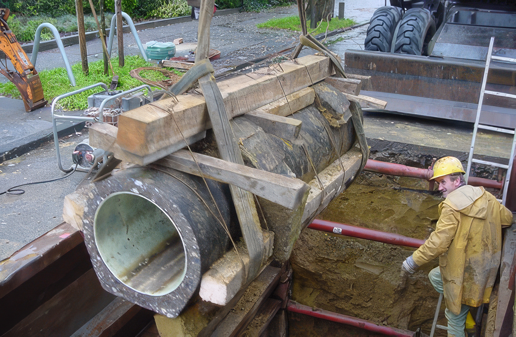
A pipe section rehabilitated with a CIPP liner is removed to examine its condition after several years in service.
One incorrect assumption can put an entire rehabilitation project on the wrong footing. The assessment of the host pipe is central to this. Even after CIPP lining, the host pipe remains part of the load-bearing system. Its structural contribution depends on its actual condition, the surrounding soil and the governing load case.
Whether the rehabilitated pipe remains structurally sound depends not only on the liner material and the calculated wall thickness. The host pipe condition, groundwater level, ovality, annular gap and material properties must also be modelled realistically. The structural design must then be checked against the properties actually achieved by the liner after curing on site. The liner can therefore only be assessed correctly as part of the combined system formed by the liner, host pipe and surrounding soil.
What network owners need to know about CIPP liner structural design
- Why the liner does not carry all loads on its own, even for host pipe condition 3
- Why host pipe condition 3 is not automatically the most critical load case
- How groundwater, ovality and the annular gap affect the required wall thickness
- Why a high modulus does not allow the liner wall to be made arbitrarily thin
- What the long-term modulus actually describes – and what it does not
- How site samples show whether the installed liner has achieved the specified properties
- Why independent structural design and independent materials testing belong together
The CIPP liner does not carry the loads alone: the much thicker host pipe remains part of the load-bearing system.
A new pipe inside the old one – but not a replacement for the entire structure
In CIPP lining, a resin-impregnated tube is pulled or inverted into the existing sewer and cured in place, for example with hot water, steam or ultraviolet light. This creates a pipe that fits closely against the host pipe. The hydraulic cross-section is largely retained while leaks in the existing pipe are sealed.
The completed rehabilitation must meet four requirements: structural stability, watertightness, durability and operational safety. Structural design therefore considers more than the liner. It assesses the complete load-bearing system comprising the liner, host pipe and surrounding soil.
This is where a common misunderstanding arises. Installing a liner does not automatically turn a damaged sewer into a completely new pipe that carries all loads by itself. The host pipe is usually much thicker and stiffer than the comparatively thin polymer liner. It therefore remains part of the load-bearing system.

How much load a damaged host pipe can still carry is a key question in CIPP liner structural design.
How the host pipe condition changes the liner’s structural role
The host pipe condition classification describes the role that the liner must perform within the existing pipe-soil system:
- Host pipe condition 1: The host pipe is leaking but structurally stable. The liner seals the pipe and resists external water pressure. Soil and traffic loads continue to be carried by the host pipe-soil system.
- Host pipe condition 2: The host pipe is cracked and ovalised but still forms a structurally stable system with the soil. The liner provides a seal and resists external water pressure. The additional ovality generates bending moments and may require a greater wall thickness.
- Host pipe condition 3: The host pipe-soil system no longer has sufficient overall structural safety. The liner supports the existing structure as part of a combined load-bearing system. As a typical order of magnitude, the liner may carry around 15 to 20 percent of the loads. It does not replace the host pipe.
Practical point for network owners:
The host pipe condition is not a calculation option that can be selected at will. It must be derived professionally from evidence on cracking, deformation, material, loading history and the pipe-soil system.
Why host pipe condition 3 is not automatically decisive
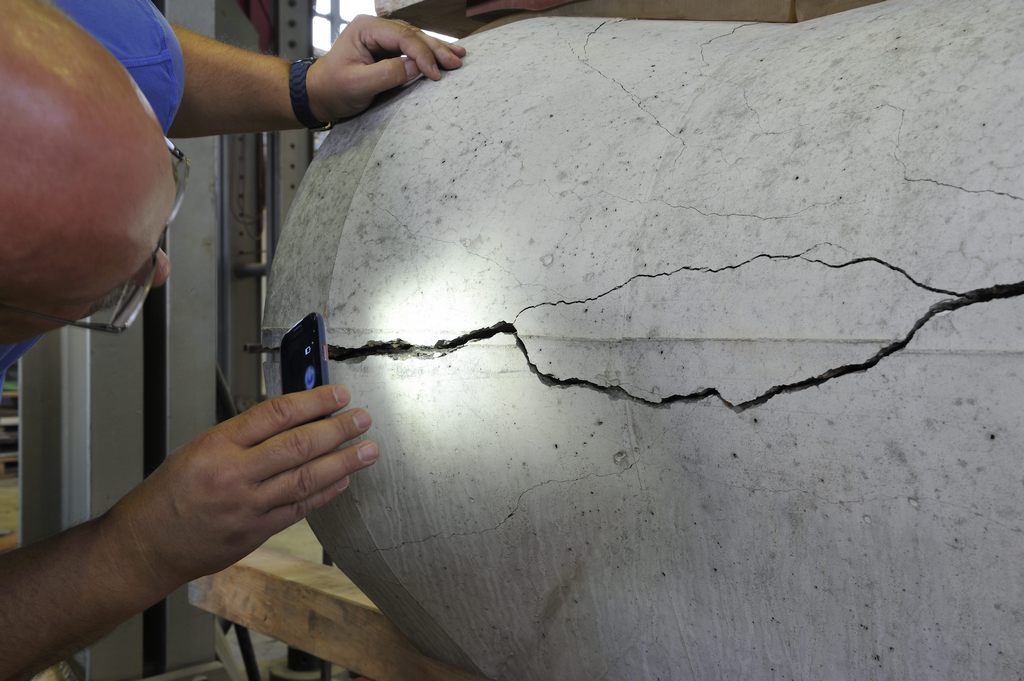
An IKT test engineer examines crack formation in a concrete pipe during the crushing test.
More damage does not necessarily mean that a greater liner wall thickness is required. Depending on the combination of annular gap, groundwater level, cover depth and ovality, host pipe condition 2 may also govern the design.
A reliable design therefore investigates several load-case combinations: minimum and maximum groundwater levels and cover depths, calculations with and without an annular gap, and the relevant host pipe conditions. The required wall thickness is determined by the least favourable combination – not by a blanket instruction to calculate only host pipe condition 3.
The cause of the damage is equally important. Has the pipe deteriorated with age, or has it been overloaded, for example by increased traffic loads or a change in cover depth? A liner cannot automatically remedy a fundamental overload or an incorrect original design of the existing system.
Play video: External water pressure forces water through the annular gap between the installed CIPP liner and the host pipe.
A small annular gap with a major effect
An annular gap can form between the liner and the host pipe after curing. A typical modelling assumption is approximately 0.5 percent of the radius. Even this small gap can significantly affect structural stability. If the liner is not in full contact with the host pipe, it can deform more freely under external pressure, increasing the risk of buckling.
The groundwater level also has more than one effect. A higher water level increases the external pressure on the liner, but buoyancy simultaneously reduces the effective soil loads acting on the host pipe. The structural analysis must identify which combination actually governs the design.
A high modulus does not automatically mean a thinner liner
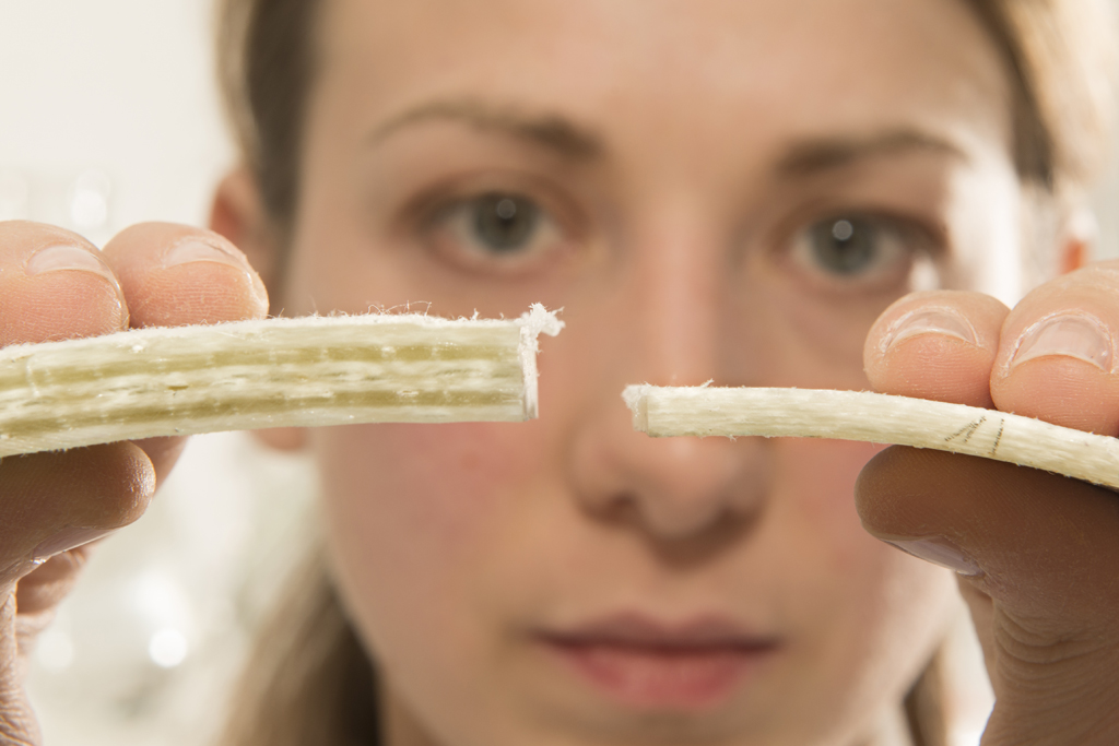
Precise measurement is essential: liner wall thicknesses can vary.
Glass-fibre liners can achieve substantially higher short-term moduli and strengths than conventional needle-felt or synthetic-fibre liners. In calculation, this creates the potential for thinner walls and less material. In practice, however, minimum wall thicknesses and, above all, the buckling check impose limits.
With a very thin wall, buckling rather than material strength may govern the design. A particularly high modulus is therefore not a licence to make the liner arbitrarily thin. Stress and stability must be assessed together.
Wall thickness and modulus must always be considered together: The IKT Testing Laboratory points out that these two parameters jointly determine the liner’s stiffness. If the installed liner falls below the structurally required composite wall thickness or the specified modulus, structural safety may be compromised.

The test measures creep, not ageing: the long-term test shows how the CIPP liner deforms under a sustained load.
The long-term modulus describes creep – not ageing
The long-term modulus is often misunderstood. It describes how the liner deforms under a load that remains constant over a long period. Polymers creep, which means deformation increases over time. The long-term modulus represents this effect in the structural calculation.
It does not describe material ageing caused by chemical attack, temperature or other environmental effects. Durability must be assessed separately. Treating long-term behaviour and ageing as the same issue mixes up two different questions.
Internal and external pressure are two different load cases

Wastewater pressure pipeline in a pumping station: internal pressure dominates during operation. When the pipeline is taken out of service, external groundwater pressure may become the governing load case.
Gravity sewer liners and pressure pipe liners are subject to different types of loading. Internal pressure mainly creates tensile stress as the pipe is loaded outwards. External pressure, by contrast, can cause instability through buckling or collapse.
A design check for internal pressure cannot simply be transferred to an external-pressure case. This is particularly important for pressure pipe liners. Even a system designed for continuous internal pressure may face a critical external-pressure load case when the pipeline is taken out of service, depressurised and exposed to groundwater.
Structural design specifies the quality – the site sample verifies it
CIPP liners differ fundamentally from pipes manufactured entirely in a factory. Their final geometry and mechanical properties are created only when the liner is cured on site. Quality assurance therefore does not end with the structural calculation.

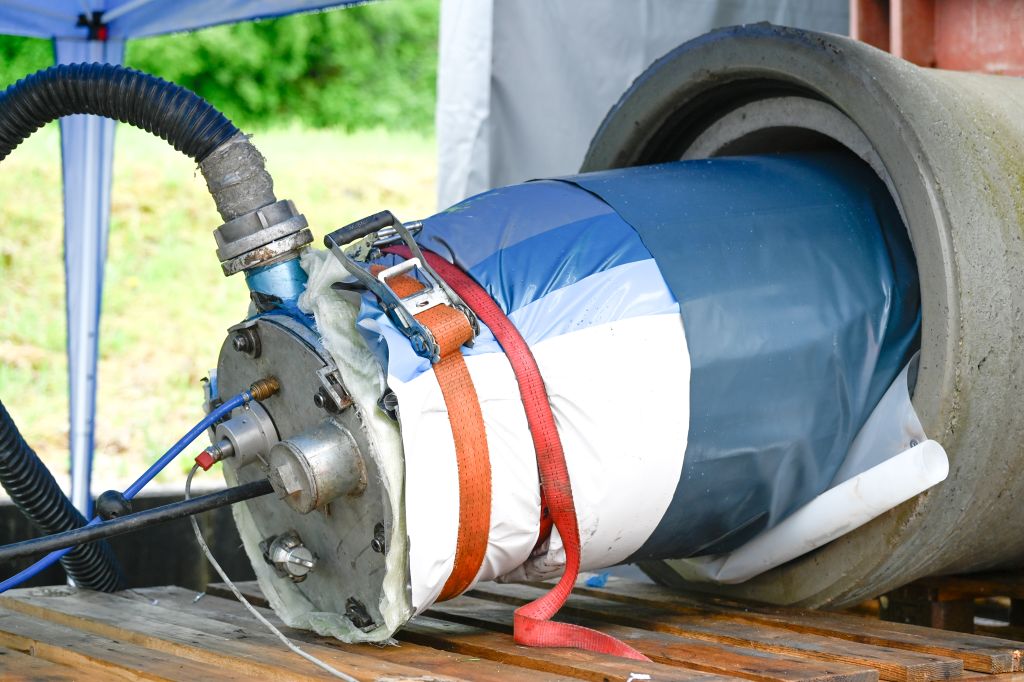
Three-point bending test on a CIPP liner sample: the IKT Testing Laboratory determines the laminate’s short-term modulus and flexural strength.
The IKT Testing Laboratory for CIPP liners conducts neutral and independent testing of site samples on behalf of network owners. The test report documents whether the required quality criteria have been met.
As a minimum test programme, the IKT Testing Laboratory specifies a three-point bending test to determine the short-term modulus and flexural strength, together with a watertightness test of the laminate. The mean composite wall thickness is also checked. Additional tests may include spectroscopic analysis, residual styrene content, filler and glass content, 24-hour creep tendency and specific gravity.
- Short-term modulus: This describes the stiffness of the installed liner.
- Flexural strength: This indicates the bending stress that the liner can withstand before failure.
- Mean composite wall thickness: This is compared with the minimum wall thickness required by the structural design.
- Watertightness: This shows whether the laminate performs its essential sealing function.
Calculation and testing must speak the same language.
The structural design defines the properties required. Materials testing shows which properties were actually achieved on site.

Neutral and independent: CIPP liner testing in the IKT laboratory.
IKT expertise in structural design materials testing and pipe soil interaction
IKT combines three perspectives that belong together in demanding CIPP liner projects:
- Independent structural design: Calculations for pipe and manhole liners, circular and non-circular profiles, and finite-element analyses for unusual geometries and boundary conditions
- Independent materials testing: Testing of CIPP liner site samples and assessment of whether the specified quality criteria have been achieved
- Assessment of the existing structure: Analysis of the actual pipe-soil system and development of recommendations for network owners
The IKT Testing Laboratory is recognised by the German Institute for Building Technology (DIBt) as an inspection body for CIPP liners and patch repair systems. It is also accredited by the German Accreditation Body for selected mechanical and technological tests on CIPP liners and polymers.
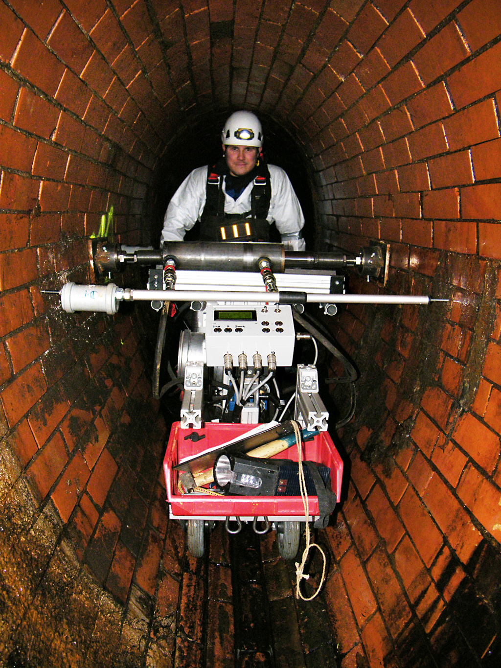
The MAC system in use: controlled micro-loads and precise deformation measurements enable a non-destructive assessment of the pipe-soil system.
The MAC method assesses the pipe soil system without destructive testing
For man-entry sewers, the MAC method developed by IKT complements this expertise. It assesses the pipe-soil system non-destructively by applying controlled micro-loads and measuring deformation. This provides a better-founded assessment of the residual structural capacity of the existing sewer – an important basis where blanket assumptions could lead to unnecessary rehabilitation or underestimated risks.
The IKT structural engineering team prepares independent calculations, assesses unusual geometries and materials, and evaluates the supplied liner and pipe quality with specific recommendations for network owners.
What network owners should check before approving a liner design
- Has the host pipe condition been derived transparently from the actual inspection findings?
- Have the cause of damage, groundwater level, cover depth and traffic loads been recorded plausibly?
- Have ovality and the annular gap been modelled realistically?
- Have short-term and long-term material properties been assigned correctly?
- Have all relevant load-case combinations been calculated?
- Are the required wall thickness and specified material properties consistent?
- Is it defined how the required values will be verified using site samples?
- Is the structural design prepared independently, or at least checked independently?

Understand the system before calculating: the finite-element model represents the structural behaviour of the pipe and surrounding soil under load.
Conclusion reliable liner design starts before the calculation
A safe CIPP liner rehabilitation is not achieved by specifying one high material value. It results from a transparent condition assessment, realistic load assumptions, an independent structural calculation and verification of the product actually installed.
For network owners, this means:
- considering the host pipe, liner and soil as one load-bearing system,
- deriving the host pipe condition from inspection findings,
- examining several load-case combinations rather than relying on a blanket worst-case assumption,
- assessing modulus, wall thickness and stability together,
- keeping long-term behaviour and ageing clearly separate, and
- using independent site testing to verify the material properties assumed in the structural design and the required wall thickness.
In short: The goal is a structurally sound, watertight and durable rehabilitation. A reliable structural design and verified installation quality are how it is achieved.
Further information from IKT
Independent CIPP liner testing:
IKT Testing Laboratory for CIPP liners
For independent structural calculations please contact:
Dr.-Ing. Mark Klameth
klameth@ikt.institute
From calculation to installation assessing CIPP liner quality with confidence
Online workshop: CIPP Liner for Sewer Rehabilitation
Anyone who specifies, accepts or tests CIPP liners needs to understand which figures are structurally relevant – and which simply look convincing.
In the IKT online workshop CIPP Liner for Sewer Rehabilitation, Prof. Dr Bert Bosseler and Dipl.-Ing. Dieter Homann, Director of Materials Testing at IKT, explain the key requirements for quality assurance from a municipality and network owner’s perspective.
Next session:
11 November 2026, 10:00-14:00 CET (UTC+1), onlineThe workshop covers:
- quality responsibility and host pipe condition classes,
- installation methods, materials, wall structure and loads,
- quality testing, site samples and liner reports,
- validation of structural calculations,
- CIPP lining in pressure sewers, and
- what to do when rehabilitation defects occur.
Related Posts
 Inspecting pressure sewer pipes: Potential, requirements and results
 IKT International Masterclass “Sewers and Pipelines: Construction, Operation and Maintenance”
 On the Starting Block: Major New IKT Product Test on “Liquid Soils”
 Pressure Sewers: UK, Irish an Dutch Sewer Network Owners Undertaking Partner Projects Alongside Current IKT Project
 IKT and IRWA: Transatlantic Cooperation on Infrastructure
 IKT LinerReport 2015: Slight disappointment on wall thickness
 Expert witness assessments and consulting
Sorry, the comment form is closed at this time.